 Ultrahigh Accurate 3-D Profilometer
Japanese / English
『Feature』
Here is our UA3P's Technology.
"Laser method / High precision probe / Software"
Coordinate measurement technology
The profilometer's coordinate system is configured with three reference flat surfaces (mirrors) independent of the stages. The length of each X, Y, and Z axis is measured to a resolving power of 0.3 nm with the laser interference method using a He-Ne frequency-stabilized laser as a light source. This suppresses the influence of squareness and straightness of the stages to achieve high-precision measurement.
- Measurement error due to coordinate axis:0.05 µm max. (up to 100 mm), 0.3 µm max. (up to 500 mm)

Measuring probe
Top-surface measuring probe/AFP
High-precision scanning and measurement of a measured object is feasible due to the use of ultra-low measuring forces.
The stylus is held by the micro-air slider, and the focus laser detects the movement of the stylus. The position of the AFP is tracked in line with the shape of the measured object to keep the measuring force constant.
- Measuring force: 0.15-0.30 mN (15-30 mgf) * UA3P-3100/4000 requires 0.05~0.30 mN, UA3P-5000H requires 0.10~0.30 mN.
- Stylus:A diamond stylus with a tip angle of 30 and a radius of 2 µm can be used.

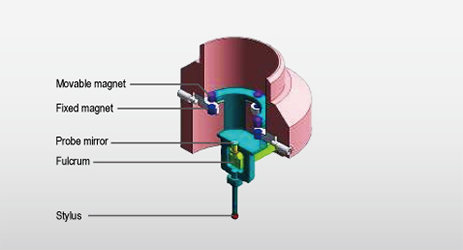
Side-surface measuring probe/S-AFP
The inclination of a probe mirror detected at high precision is fed back to the XY stages to enable scanning measurement with low-contact force (0.3 mN).
This enables measurement without deforming resin products, such as a lens barrel.
- Measuring force: 0.3 mN (30 mgf)
- Measurement accuracy: ±0.15 µm (when measuring 90° inclination)
- Maximum measuring angle:Horizontal measurement:45° - 90° (angle relative to horizontal surface), Vertical measurement:80° - 90° (angle relative to horizontal surface)

Software
Achieving high-speed and high-precision measurement with easy operation Supporting any design information. An installation error in the measured object is three-dimensionally corrected to enable accurate profile measurement.
Design information input
Supporting any design information
- Optical design formula
- 3D point group data

Centering and measurement
The center of the measured object is found to scan and measure on its axis and plane.

Alignment
Numerically identifying a difference between the measurement data and design formula.

Top side surface evaluation technology
By synthesizing the top-surface data and side-surface data of a measured object, decentering and inclination of the optical axis of a lens or a mold can be evaluated with reference to the side surface.


